Thermal bowing
Thermal bowing is when the bottom of the pipe is subject to a different temperature than the top of the pipe involving little thermal conduction or convection. The result is that the pipe curves, similar to how a bimetallic strip bends. The cold bottom gets shorter, while the top of the pipe stays at the same length.
This is especially the case for cryogenic lines when they get started up from an ambient temperature condition. Cold liquid enters the pipe and settles at the bottom due to gravity. The bottom of the pipe cools down rapidly while the top remains at ambient temperature for a period of time. This period is made longer for stainless steel because its thermal conductivity gets even worse at lower temperatures. Than compared to lets say Aluminum.
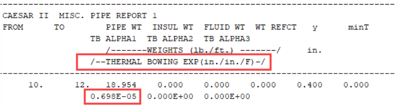
In Caesar 2 this can be calculated using thermal bowing at the special input tab.
![]() You have to enter a temperature difference.
Positive temperature difference: Bottom of pipe, Lower temperature
Negative temperature difference: Bottom of pipe, higher temperature
You have to enter a temperature difference.
Positive temperature difference: Bottom of pipe, Lower temperature
Negative temperature difference: Bottom of pipe, higher temperature
The program will use the design/working temperature as maximum temperature, and then do the differential from that.
Other cases
Thermal bowing can also happen from thermal conduction of something outside the pipe or inside. For example you can have condensate in the pipe cooling that part down, or if the pipe gets partially flooded. Another scenario is external heat sources like sun exposure on one side of the pipe, or a nearby hot process line running parallel.
Cryogenic startup
Generally a cryogenic pipe would not get filled from an ambient situation, partly because of this but also because of ice formation. First you would need to “dry” the air, generally with cold nitrogen. This process removes moisture that would otherwise freeze and block the line. This means that a system that is “always” cold except during start up where it slowly gets cooled down, does not require calculating for thermal bowing.
When to include: Some piping in a cryogenic system is not constantly in use, this is especially the case with ambient vaporizers. An ambient vaporizer is often employed in a cyclical nature to allow the ice to melt. During each cycle, the pipe goes from ambient to cryogenic temperature relatively quickly. Whenever a part of the pipe can be cooled down in this way, you also have to take into account thermal bowing.
Piping design and process influence
The design of the piping and process of the piping also has a large influence on potential thermal bowing concerns. The conservative way would be to apply thermal bowing to everything, but like with a lot of things in pipe stress, when you run into problems you can go deeper.
Piping design
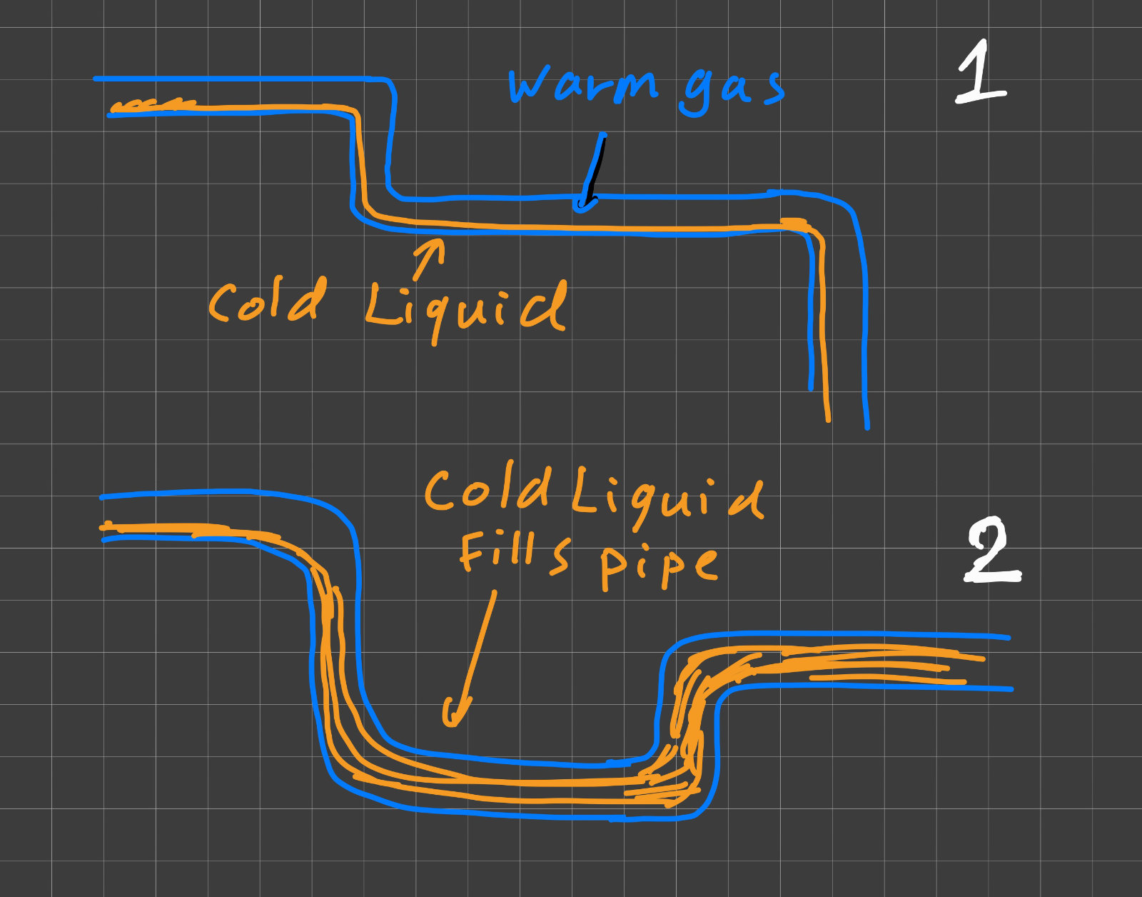
The way the piping is laid out will tell you about how liquid will be in part of the pipe or has to completely fill the whole pipe. In the first example the way the liquid flows will always leave the possibility of having a separate gas and liquid phase. This two-phase flow creates the temperature differential between bottom and top. The second example shows that having a small riser will make the pipe always completely fill up with liquid. You can design problematic longer pipe lines with a riser to reduce temperature difference between bottom and top of pipe, but this is not guaranteed to fix the issue and can cause process issues.
Process design
Even in a predictable operating scenario, you have to also look at the process. These questions help determine how severe the thermal bowing could be:
- How much flow do we have?
- What is the speed in m/s?
- How long does it take to fill the pipe completely?
- If the pipe is designed like example 2, how much extra time does it take for the downstream user before they are supplied with cold liquid?
- How is the liquid driven to the user? If there is little pressure behind it, will a gas lock cause the whole process to stop?
Low flow rates mean longer exposure to the thermal gradient, which can result in higher bowing stresses. High flow rates will fill the pipe quickly, reducing the time the pipe spends in a partially filled state. The stress created by thermal bowing are the largest when the pipe is filled between 25% to 75% of its height.
Caesar 2 Issue
The issue with Caesar 2 is that thermal bowing is applied to all the load cases. You can’t create a different case without thermal bowing (that I know of). This makes it hard to apply thermal bowing to a larger system where not all pipes are subject to thermal bowing, or even are cold.
My recommendation is to make a separate calculation of the pipe subjected to thermal bowing, especially for large temperature differences. This also means you have to decouple this piece of piping from the rest of your model. Here is the approach:
- Decouple the pipe by adding anchors or a set of supports so the pipe has no influence on the rest of your piping. This creates a boundary condition that isolates this pipe to be able to analyse it seperately.
- Create a different pipe stress calculation with just that pipe.
- Add thermal bowing to that separate pipe stress calculation file.
- Optional: create a copy without thermal bowing to check if there are no issues for long term running, or keep this in the original larger model.
This method is more work but gives you proper control over which pipes see thermal bowing loads. Especially useful when adding thermal bowing makes other piping worse or gets really unreasonable for the real situation.
Observations from research
This is something I came across when researching this subject. I would expect that if I have a large pipe line of lets say 15 meter, the start of the pipe would have a larger temperature difference compared to the end. The cold liquid enters at one point and you would think the first part it hits, cools down first.
But because the thermal conductivity of stainless steel drops at lower temperatures and the convection is low for liquid that flows slowly over the pipe, it tends to be that the middle of the pipe or the end will cool down faster. The liquid entering the pipe is cold, but the thermal conductivity drops, while the flow stays laminar. Further in the line more evaporation happens, the increased turbulence and higher thermal conductivity allows it to catch up.
This also means that it doesn’t matter much how long the pipe is for the characteristic temperature difference of the pipe, when talking of a range at less than 50m. Beyond that length, the behavior becomes more complex.
Sources
Tummescheit, Hubertus et al. “Simulation of Peak Stresses and Bowing Phenomena during the Cool Down of a Cryogenic Transfer System.” (2008).
Flieder, W. G., Loria, J. C., and Smith, W. J. (September 1, 1961). “Bowing of Cryogenic Pipelines.” ASME. J. Appl. Mech. September 1961; 28(3): 409–416. https://doi.org/10.1115/1.3641720
Pipe stress engineering (2009) by Liang-Chuan Peng & Tsen-Loong Peng