Dealing with Impossible Nozzle Loads
An important part of pipe stress is not exceeding nozzle loads. Connections on vessels or equipment tend to be weaker than the piping itself, which often shifts the focus from reducing stress in piping to reducing nozzle loads.
Sometimes you will come across an incredibly low nozzle load, this can be categorized in 2 ways:
- A weak and flexible part like a heat exchanger.
- Rotating equipment like turbines or pumps.
These categories can be treated in the same way in pipe stress software, but you will find that category 1 can be almost impossible to comply with. Turbine or pump manufacturers are well-versed in nozzle loads and designing to relevant standards. This is not the case with simple heat exchangers, where very often no formal pipe stress analysis is done and no nozzle loads are given. The reason behind this is that the piping is relatively low-risk and often the pipe route is made on-site.
When you do ask for nozzle loads for Type 1 equipment it comes back very low, so low that any small expansion from a pipe will overload the nozzle.
Why Are These Nozzle Loads So Low?
Stress Category
When you receive an allowable nozzle load, this is a set of figures that can be applied over the lifetime of the equipment without breaking it. The load can be Sustained (primary) or from temperature (secondary).
Sustained loads tend to be more dangerous than secondary, but both can equally well destroy the nozzle, or not destroy the nozzle. This is a really important part of pipe stress and any analysis we want to do for these nozzles.
Look at this example:
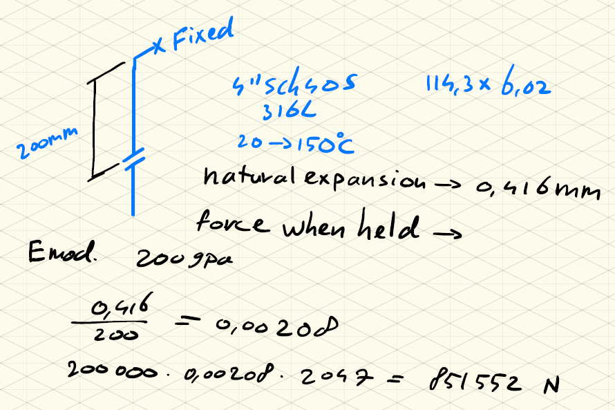 [Article content: A relatively short piece of pipe wants to expand 0.4mm because of thermal expansion. If you hold it back it exerts a force of 851,000N or about 85,000kg.]
Next I will create a similar scenario with the force being primary instead of secondary.
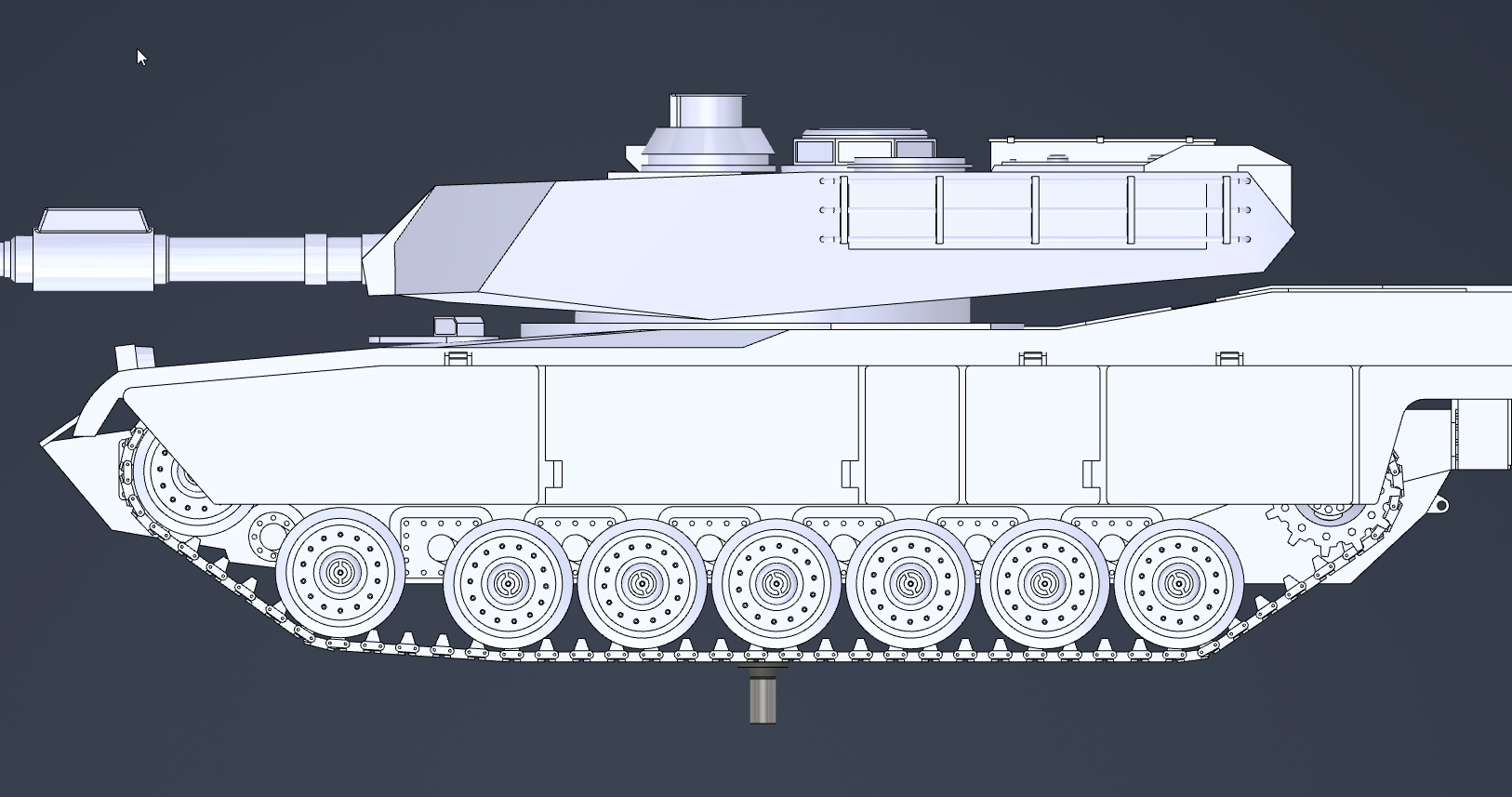 [Article content: This is an M1 Abrams tank, it weighs a bit less than the example above at about 70,000kg.]
In this example, you can see a similar amount of force in each situation, with different results.
In the secondary load, the nozzle/equipment cannot handle the high load. It will start to deform, this deformation allows the pipe to expand and this reduces the force. This is linear so:
Expanding by 80% will reduce the force by 80%.
The pipe wants to expand by 0.4mm which is not that much so the actual nozzle load will be much lower.
The fixation point is going to be a pipe support and will undergo the same force as the nozzle (basic physics, in a static situation each force will have a counteracting force). This support will also flex, reducing the loads on the nozzle.
When we go to the primary load, this is not the case at all. After the nozzle starts deforming, the tank does not get lighter, it will stay exactly the same. It’s just going to keep going.
I told you earlier that secondary loads can still be equally dangerous as primary. How does that happen? Let’s change our secondary stress example by making the pipe longer.
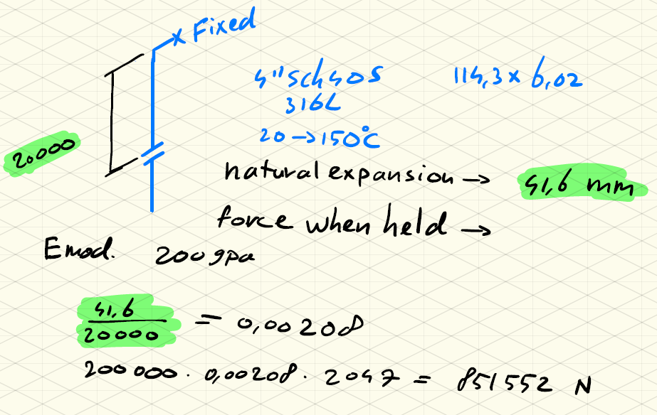 [Article content: The interesting thing is that the force the pipe exerts stays exactly the same, but the situation would become worse.]
Why is that? The actual expansion is much higher at 41mm.
If the nozzle and pipe support move by 0.4mm this only reduces the total load by 1%. Most probably at 41mm the nozzle and/or pipe support will break, maybe not right away but definitely in fatigue.
If you are responsible for giving nozzle loads for your equipment, without knowing what is going to be connected to it, you have to assume the worst-case scenario which will be primary. No matter what actual flexibility the nozzle has, you have to assume the nozzle load will constantly be applied.
Materials
Looking at the construction of a larger heat exchanger, they are often made up of headers and multiple tubes together, these headers and tubes cannot be tightly held down, because of their thermal expansion. Whatever the nozzle load is, force has to be transferred to the construction itself, with significant (bending) loads and high stress as a result.
It doesn’t help that these are not made of steel, but aluminum or copper. These materials have much better heat transfer properties but are also not as strong or stiff. (Stronger alloys are of course available but not feasible in the amounts needed for a heat exchanger)
Young’s modulus is the measure of the stiffness of a material. A higher number will indicate a stiffer material.
- Steel - ~200GPa
- Aluminum - ~70GPa
- Copper - ~130GPa
Type 2 Nozzles
ISO 5199 is a code with technical specifications for centrifugal pumps. It also gives standard nozzle loads to use.
There is also a table of maximum displacement based on the type of pump under nozzle loads. This is between 0.15 and 0.25mm.
These displacement values are easy to hit, even with short pipe spools. So they will always be problematic when running a pipe stress analysis. It’s a good thing that pump suppliers will almost always give nozzle loads that you can actually work with.
What About Type 1?
We’ve explored the intricacies of nozzle loads in flexible parts. It becomes clear that a nuanced approach is required for evaluating nozzles for this kind of equipment.
Understanding the fundamental differences between sustained and secondary loads, and how they impact equipment, sets the stage for our next discussion. In my forthcoming article, I will delve into practical and theoretical strategies to navigate these challenges effectively. Some of my strategies will make you go out of pipe stress software and give tips on analyzing the system directly.